


Find Parts For Your Vehicle
Featured Categories View All »


Top Products
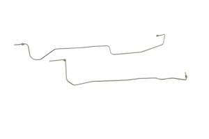
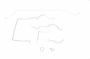
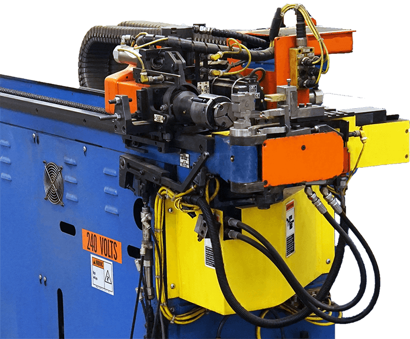
Classic Tube is the leader in the preformed tube bending industry. We can iterate virtually identical parts on an infinite scale by leveraging industry leading CNC tube bending technology non-contact laser scanning, and our highly experienced engineering team. These allow us to produce long lasting tubing with extreme accuracy, competitive pricing, on schedule delivery, and knowledgeable customer service.